If I understand it correctly, the customer would like to perform measurements according to CISPR 25 using the Agilent/Keysight N9038A.
The customer is referring to table 2 as it is part of the CISPR 25 Edition 3.0: 2008
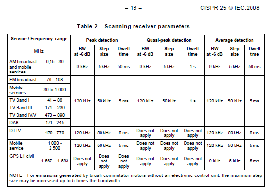
- CISRP25 Table 2
- CISRP25-table2.png (31.54 KiB) Viewed 11518 times
Based on settings of the RadiMation TSF configuration, the customer is performing a test using the settings:
Frequency range: 100 – 150 MHz
Step frequency: 50 kHz
RBW: 120 kHz
Measure time: 5 ms
Trace-detector: QP
Based on these settings, 1001 individual frequencies in the 100-150 MHz range will be measured. In combination with a measure time of 5 ms, an expected total measurement time of 1001 * 5 ms = +- 5 seconds can be expected.
However the settings in the TSF are different from what is required from the Table 2 from CISPR 25. In Table 2 there is no specification for the frequency range of 100 MHz- 150 MHz at all. And also in Table 2 there is an explicit specification of a minimum dwell time (which is measure time) of 1 second for the Quasi Peak detector.
The reason for the minimum dwell time of 1 second for the Quasi Peak detector is logical, as the principle working of the quasi peak detector needs some time to determine the correct measurement value. The correct setting for the measure time in RadiMation is thus 1 second. The total measurement will then take 1001 * 1 second = 1001 seconds = +- 17 minutes.
I also expect that the Agilent/Keysight N9038A doesn’t allow to use the QP detector in combination with the 5 ms measure time. And based on that I expect that the N9038A will require more time (at least +-17 minutes) to perform the measurement with the QP detector. In discussions I have had with Agilent/Keysight, I have learned that the minimum effective measurement time for an EMI compliant detector is 1.4 second in the N9038A. Thus in the configuration as configured by the customer, the N9038A probably requires 1001 * 1.4 seconds = 1401.4 seconds = +- 23.4 minutes.
I hope that this explains why the measurement takes longer than expected.
And this also explains that I cannot make a modification in our device driver to speed up the measurement of the N9038A.
Then the next question, probably will be: How can the customer perform this measurement in less time?
As it is described in section 4.1.3 of CISPR 25, it is allowed to perform the measurement using the Peak detector, and only measure those frequencies with a Peak-detector value that are above the QP limit, using the QP and/or Average detector.
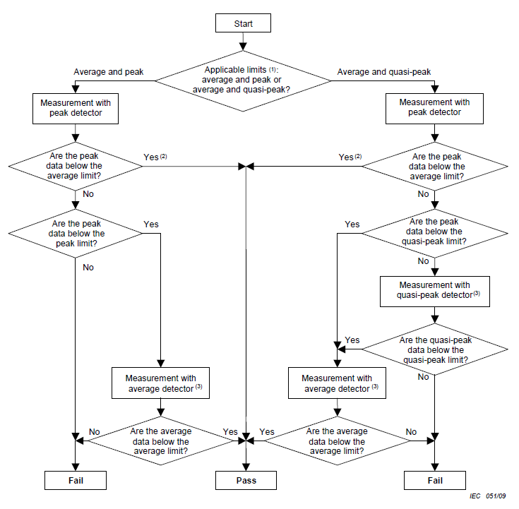
- CISPR25 Measurement flowchart
- CISRP25-flowchart.png (42.87 KiB) Viewed 11518 times
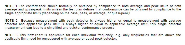
- CISPR25 Flowchart notes
- CISRP25-notes.png (20.85 KiB) Viewed 11518 times
It is explicitly described in Note 3 that this flowchart should be interpreted for each individual frequency, and only those individual frequencies that are above the Peak limit should be re-measured using the QP and/or Average detector.
This is not a problem at all to be configured in RadiMation.
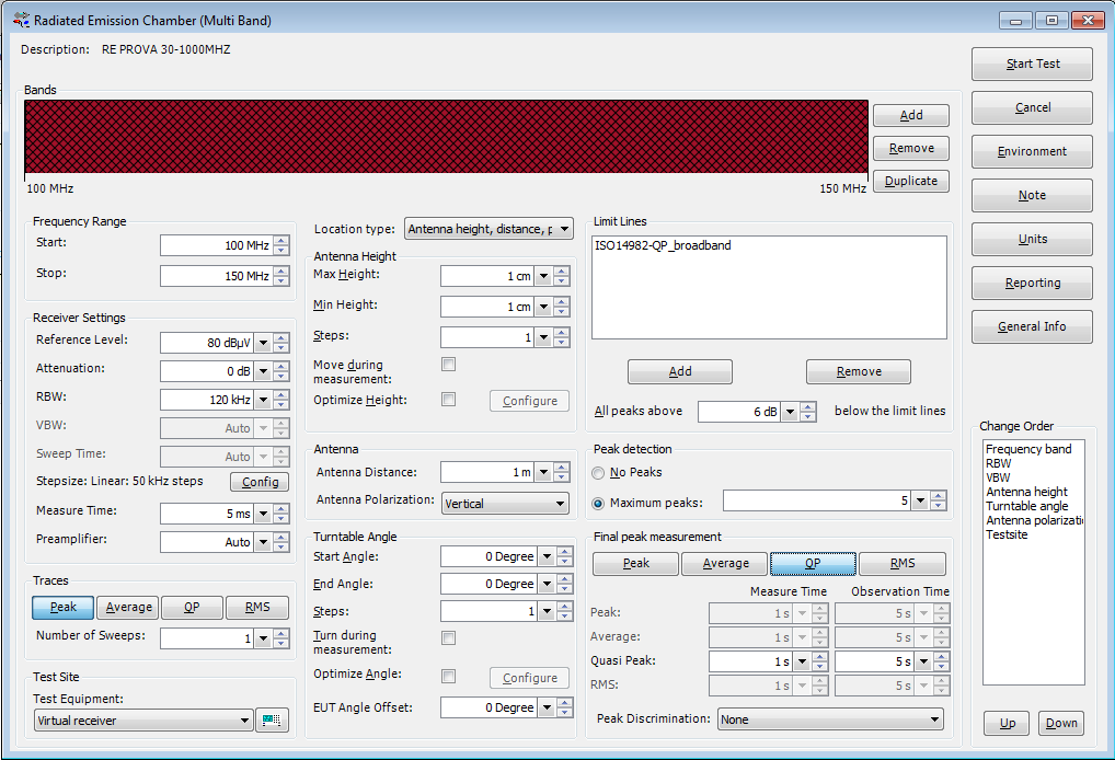
- Improved RadiMation TSF Configuration
- Improved-RadiMation-config.png (62.29 KiB) Viewed 11518 times
Just configure RadiMation to perform a measurement from 100 MHz to 150MHz, with 50 kHz steps, using the Peak detector.
Specify the limit line and the maximum number of peaks that should be detected (for example 5). And configure the QP detector as a final peak measurement, using a measure time of 1 second.
When this measurement is performed, it will result in a fast measurement of 5 seconds, using the Peak detector. RadiMation will then compare the measured peak detector values to the specified limit. Any value that is above the limit line will be marked as a detected peak. The measurement will be halted, which allows the test-engineer to add more peaks, or exclude some detected peaks. When the list of detected peaks is as desired, the test-engineer can press the ‘Automatic’ button again, and the final measurement will be performed on the detected peaks. This final measurement will be performed using the QP detector using a 1 second measure time. RadiMation will however monitor the QP detector for a period of 5 seconds (the observation time) to determine the highest value during that 5 second period. The final peak measurement of the QP detector will be compared to the limit line again to determine the pass/fail status.
In the above configuration only the 5 highest measurement values above the limit line will be marked, but this maximum peak count can be configured as desired.
The CISPR 25 requires that also the Average detector value is measured. It is possible to also activate the ‘Average’ detector for the Final peak measurement. In that situation, the detected peak will also be measured using the Average detector, and the resulting measurement value will be compared to the Average limit line.
I hope that this explains how the measurement as desired by the customer can be performed using our RadiMation software.
If you still have questions on how to use RadiMation to perform EMC measurements, please let us know.